Britlift look at the misuse of spreader beams in the industry, providing an explanation as to the issues
The misuse of spreader beams is still shockingly common in the industry. Here we show some images and diagrams and discussing what is incorrect and why.
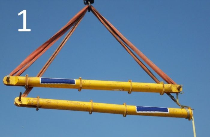
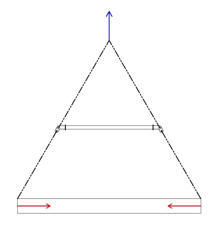
The image above was taken of a very recent lift within the UK in 2017. One of the companies involved used this as a promotional image. Now I’m sure many of you have already spotted the error with this lift, but I’m going to look at not just what is wrong, but why it is wrong.
A spreader beam is subjected to a crushing force – compression.
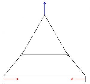
To help explain what is going on in the above image, I’ve redrawn it below:
It is difficult to be sure from the photo, so to start with in figure 2 I have assumed that bottom slings maintain the same angle as the top slings (it actually looks as if the ISA angle widens which I will deal with later in this post).
What is happening here?
Let’s get straight to the point then, the beam in this image isn’t being used correctly, in fact, you could say the beam in this image isn’t even being used!
In this example, the compression force is entirely taken by the load itself – indicated by the red arrows in figure 2 above. When presented with the above scenario, many would argue that the spreader beam would perhaps share the compression force with the load, but this is not the case.
The first point to make is that if the spreader beam was removed from this there would be no change to the sling angle and no change to the forces in the load.
The reason the load takes all of the compression in this example, is because this is the point at which the force pulling downwards (created from the weight of the load) travels into the angled sling. As discussed in my first article, it is the angled sling which creates the inwards (compression) force, and in this example this force acts at the point where the angles change.
Higher up the rig, where the spreader beam is placed there is no change in the angle of the force from the bottom slings to the top slings, therefore there is no resultant force created to compress the spreader.
To help put this into perspective I have redrawn the diagram with the slings underneath the spreader beam having a wider ISA angle than those above.
Let’s compare this new diagram (figure 3) to the first (figure 2). Starting at the bottom with the load, and the bottom set of slings, we have a very similar situation. The load will still be in compression for the same reasons as in figure 2. When we move up to the spreader however, we now have a slightly different situation. We now have a change in angle between the bottom slings and the top slings which means we will also have a resultant force passing into the spreader beam. In this case however the force passing into the beam will be tension (pulling force) and not the compression (crushing force) the beam was designed for.
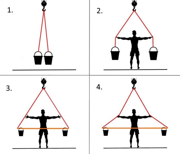
In figure 4 image 1, two buckets are hanging from separate slings in a crane hook.
In figure 4 image 2 a man has stepped between the buckets and is pushing the slings apart. The slings want to hang straight so the man is experiencing a compression force on his arms. This is similar to the forces on a spreader when it is being used correctly.
In figure 4 image 3 the buckets are now connected by a bar. The slings are at an angle from the bar to the hook and this angle does not change as they pass the man’s arms. Here the man is doing nothing and is experiencing no compression force.
In figure 4 image 4 the bar has been lengthened and the man is now holding the slings in. Quite clearly here the man would be experiencing a pulling force. This is the same as the spreader in figure 3, the change in angles here produces a tensile force.
So why is this misuse?
The example in figure 2 shows a beam that is not really being used, in this example it is unlikely that a beam would fail – the issue is more likely to be with the load. If it has been assumed that the spreader will be taking the compression forces out of a load, where in reality the load is bearing all of the force, the load could be damaged or even drop.
The example in figure 3 is much worse, the same problems are present as in figure 2, but in this example the beam itself could fail as they are not designed for tension. True tension and compression are similar forces, but a component such as the bolts in a modular spreader are calculated under the assumption that they will see stresses as a result of shear and bending – axial tension would add to these forces, something which was not allowed for in the design process.
In summary
In the example above, the sling angles below the spreader were the particular area where misuse was present. To be clear, we are not suggesting that the slings below a spreader cannot be angled at all. In fact, it is mandatory to allow for a 6 degree (from vertical) angle as a minimum in accordance with the current EU harmonized standard (EN 13155:2003+A2:2009) for the design of spreader beams. In the case looked at here the angle was just a little too far away from vertical.
Article by Anthony Culshaw (TD Britlift)
Other examples: