
The technical team at structural warranty specialists Advantage Insurance (AHCI) take a look at what constitutes best practice for foundations in 2020
For this construction-focused edition of PBC Today, we’ve taken a look at the various options for foundations most commonly used within the construction industry today, and have also considered the key variables which will affect the final choice of foundations at the design stage.
We also provide information on current building regulations and British Standards intended to ensure foundations are designed to optimally fulfil their purpose. It goes without saying that mistakes at this early stage of the construction process can prove to be costly to put right and can be detrimental to the building’s structure and longevity.
The function of foundations
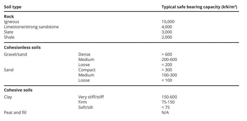
Essentially, the function of foundations is to ensure effective and balanced transfer of structural loadings acting upon the ground supporting the building while preventing the overstressing of that ground. The substrata of the ground will stand as one of the most important factors in choice of foundation.
Strip Foundations
Strip foundations are one of the most commonly used foundations. They are generally used for ground where the subsoil is of a good bearing capacity. Strip foundations are designed for structures where the load is relatively modest, such as, low-to-medium rise domestic buildings. The traditional form of most house construction allows for the use of strip foundations.
Strip foundations consist of a continuous strip of concrete formed centrally under loadbearing walls. The continuous strip acts as support for which walls are built and is to a width to spread the load evenly of the building on the ground underneath it, supporting it. This is known as a ‘uniformly distributed load’ (UDL) and refers to the even transfer of a structure’s loading at foundation level upon subsoil capable of supporting the load without undue compaction (See strip foundation table).
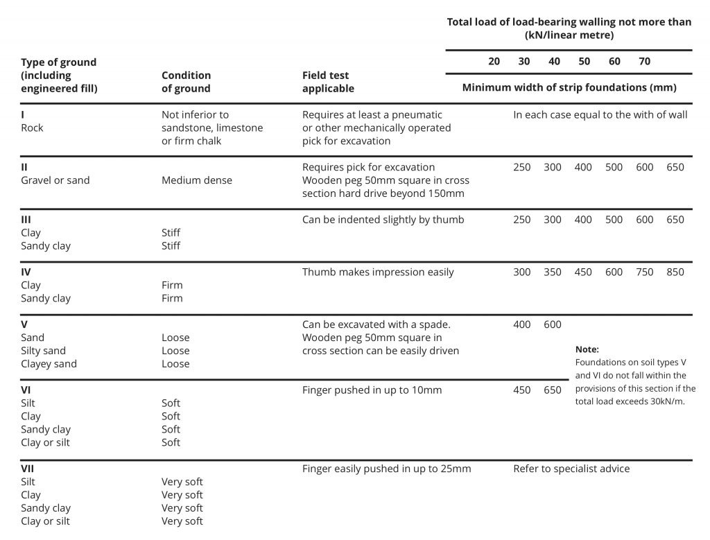
The minimum requirements for the depth of strip foundations are dictated by local ground conditions, but, as a rule, the depth of these foundations should be at least 450 mm below finished ground level to avoid damage from frost action in frost susceptible ground. (See BS 8004 for correct guidance on depth and width of foundations).
Deep foundations – Piled foundations
Piles are often described as columns within the ground. They can be an unpopular choice of foundation due to the requirement for heavy equipment and the expense and additional time this involves.
For sites with less favourable ground conditions, piled foundations are often the only plausible solution if a project is to commence. Piled foundations are installed where ground quality close to the surface is poor or variable. The use of such a deep foundation in these conditions is often obligatory. Generally Piled foundations are categorised into 2 different types, and they differentiate in type due to their method of installation.
Displacement Piles (Driven)
Displacement piles are installed by forcing or driving a solid pile or hollow casing into deeper substrata, which displaces the surrounding ground. This method of driving a pile into the ground is one that requires a lot of force and energy. A driving rig is commonly employed for this process. This technique can create difficulties due to the noise levels and vibration generated as a result of the driving operation. These undesirable characteristics often make this method unsuitable for congested sites where adjacent buildings may be structurally affected, or areas where noise nuisance is prohibited. (Code of practice, BS 5228 deals specifically with piling noise and vibration).
Replacement piles (Bored)
In contrast, replacement piles are installed by removing a volume of soil and ‘replacing’ it with load supporting piles. The soil is removed by using a hollow weighted grab or a rotary boring auger. The excavation is prevented from collapsing by introducing a hollow shell, normally made from steel, or the viscous liquid, Bentonite. The bentonite is then displaced by concrete as it is poured into the excavation. There are four generic forms of replacement pile, see below:
- Bored cast in-situ piles (small diameter)
- Bored cast in-situ piles (large diameter)
- Friction piles and end-bearing piles
- Grout injection piles
Connection to piles
In many cases, piles are subjected to point loads. It is often the case that the load of the building will exceed the capacity of one single pile column. Therefore, piles are frequently grouped together to support the applied load. The connections to the end of piles are called Pile caps; they are used to link the heads of adjacent piles and to provide a platform for a buildings load. Ground beams are introduced to pile connections in order to uniformly distribute the load (UDL) of traditional built dwellings, therefore, acting as a suitable interface between walls and pile.
The ground beam is normally cast in-situ by using shuttering around pile caps. The concrete is poured into the shuttering, and is normally reinforced with a steel-rebar ring beam cage. Concrete spacers are installed to the steel reinforcement to ensure that, when the concrete sets, there is adequate coverage of the steel to avoid the steel corroding (See BS 7937 for guidance on concrete spacers).
To conclude, piled foundations should be installed by an appropriate specialist under a Structural Engineer’s supervision. All piles should be suitable for their design load. Once installed, piles should be integrity tested to ensure the piles can support their designated load.
Raft foundation
Raft foundation designs may be proposed and submitted by a suitably qualified engineer if they are fit for purpose and cost-effective. It is essential the raft foundation provides adequate bearing capacity, accounting for latent settlement characteristics, which often depends upon the strata make up. The imposed load is distributed over a wider area, usually the entire footprint, and can be thought to ‘float’ on the ground in a similar manner to a raft floating on water.
They are constructed using reinforced concrete slabs of a consistent thickness throughout, generally 150mm-300mm with a waterproof membrane above. To minimise the likelihood of cracking, steel reinforcement can be integrated into the concrete raft; this method is more cost-effective in comparison to adjusting the thickness of the slab. Especially where there are complex ground conditions (contamination, groundwater, trees etc.) or where additional support is needed for specific loads. The types of raft foundation are as follows:
- Solid slab raft
- Piled raft
- Slab beam raft
- Cellular raft
The type used will correspondingly depend upon the nature and characteristics of the proposed scheme. Some factors to consider include:
- Is there a basement?
- The floor area, height and loads
- Differential settlement
- Where it is unfeasible to construct individual strip foundations to cover the footprint area
- Where it is unfeasible to excavate to a substantial depth.
Overall, Raft foundations incorporate the floor slab with the foundation, resulting in less material and time being used which in turn reduces the cost. That being said, they can sometimes be prone to erosion around the edges and tend to be less effective on concentrated areas of structural loadings.
AHCI
Tel. 0845 900 3969
Twitter: @AdvantageLDI
Please note: this is a commercial profile.


