Today’s laser scanning equipment can provide a complete digital image of any structure – top to bottom; slabs to columns; before, during and after construction
The quantity of data is nearly limitless. A series of laser scans stitched together reveals everything about a building; perhaps most importantly, how closely it conforms to what was specified in the contract documents.
This creates a dilemma for contractors: you want to know if you’re in tolerance, but what if you aren’t? Knowing if the work is at the specified location is good to check and refine your work, but do you want the owner and the designer to know if every feature of the structure is exactly as intended, meeting all the tolerances, just in case it’s not? What if the scan reveals that a well-performing floor nonetheless has spots that are out of tolerance in terms of floor flatness or levelness? That walls are not perfectly plumb? Or that dimensions of stair risers and treads are slightly out of tolerance?
To try to make sense of the potential impact of this kind of data, the American Society of Concrete Contractors (ASCC) held a workshop during the 2018 World of Concrete with representatives from all segments of the industry.
“We want to ride this wave, not drown under it,” said workshop organiser and ASCC technical director Bruce Suprenant. The objective was to “develop direction and content for a draft of an ACI-ASCC Committee 117, Tolerances, document, Guide to the Use of Laser Scanning for Concrete Construction Tolerances”.
Point cloud
A laser scan creates what’s known as a point cloud: millions of points that are oriented to a benchmark in three-dimensional X, Y, Z coordinates. These coordinates, or points, define an object’s shape, be it a truck or a coffee cup or a building or a floor. The laser scanner operates robotically to collect all these points by shooting out a beam of laser light and collecting the reflected light. To create a point cloud, multiple overlapping scans are performed and the results are stitched together.
To get good scans, the area needs to be clean and free of obstructions – all cords picked up and the floor swept. Some contractors place their tools and materials on carts that can be rolled out of the way. The scanner is positioned on a levelled tripod and calibrated. Targets are often placed on columns so the different scans can be aligned during the stitching-together process. The operator turns on the scanner and then moves behind the scanner as it works.
Scans can be performed multiple times in the same area while construction proceeds. Loay Hanthel told workshop attendees that Largo Concrete scans an area three or four times: before reinforcement is placed, when the steel has been positioned, shortly after concrete placement and after shores have been removed. This allows the Tustin, Calif., company to know exactly where all the steel is, slab thickness and whether everything is in tolerance. This data doesn’t go to the project owner, but is retained for internal use or if a dispute arises.
“Largo is using scanners to evaluate their level of accuracy in all parts of the construction,” says Clinton Gray, technical director at Faro Technologies, a scanner manufacturer in Lake Mary, Fla. “Scanning over time shows if anything is deflecting, which would not be the contractor’s fault.”
F-numbers with scans
Scanning a concrete floor with a 3D laser scanner is an application that has great potential to improve construction quality. The older methods for measuring the quality of a concrete floor involved using the Dipstick from Face Construction Technologies or the F-Meter or D-Meter from Allen Face and Co.
Determining F-numbers relies on ASTM E1155, Standard Test Method for Determining FF Floor Flatness and FL Floor Levelness Numbers. The standard was updated in 2014 to allow the use of a “laser imaging device”; but didn’t change how results are to be reported or the test’s limitations, such as measuring within 72 hours, having sample measurements greater than 11 feet, and taking no measurements within two feet of slab edges, columns or penetrations.
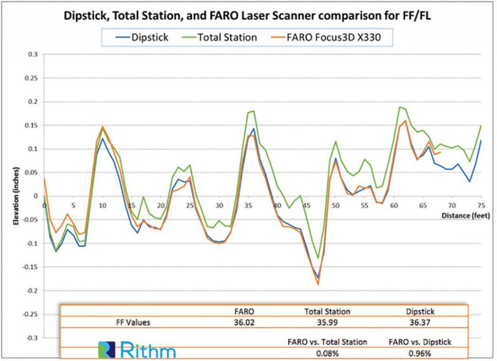
“We spent three or four months doing side-by-side comparisons and found them very comparable,” says Josh DeStefano, construction technology leader for DPR Construction in Redwood, Calif. “But I had to prove the validity of the scanned F-numbers to my internal teams. One way we did that was to compare Dipstick data we were getting from the test companies with F-numbers generated from scans we did on the same days.”
The results convinced company leaders the laser-scanned F-numbers were valid.
To get F-numbers with a laser scanner, the floor is scanned such that the individual scans overlap to cover the entire floor. Scans are positioned such that columns don’t interfere. The software uses the data to calculate FF and FL numbers, both the overall average and local minimums. However, F-numbers don’t tell the whole story.
“Producing F-numbers with the laser takes about the same amount of time as with a Dipstick,” says Faro Technologies sales engineer Brady O’Brien. “It can be set up to run a line like a Dipstick or F-meter but produces a digital record instead. A better way to use the data is to not use traditional lines. This is a whole new way of measuring a floor. It produces a heat map of the entire floor not on a straight line. It exposes the whole deck. We shift from a cross-section on a line to the whole deck.”
Contractors are understandably concerned that data revealing every minor imperfection could create disputes with project owners.
“We encourage contractors to scan the floor but not to give the data to the owner,” says Philip Lorenzo, president of Rithm, a developer of software that processes scan data. “Just give the owner the F-numbers. That’s what they specified and are paying for. If they want something beyond that it’s an add-on, an extra that must be paid for.”
“Most of the time we use the data to understand where we might have issues,” says DeStefano. “Sometimes we overlay a heat map on to a floorplan so we can see any areas the client might be concerned with that might need some rework. Or maybe we communicate with other trades to ensure we don’t have issues with the space when it’s finished. We’ve had clients ask questions about areas of their floor and were able to show them the data. But first we have to educate them on what the standards say and what we’re required to analyse and provide.”
“There’s been some pushback from contractors on this,” says Faro Technologies’ O’Brien. “They fear they’ll be forced to rip out the whole deck when the corners fail to meet the tolerances. This may eventually create a change in the whole industry to move away from F-numbers to something like ‘no deviation in the floor greater than a specific plus-or-minus tolerance’.”
Wet scan
One promising application is wet scanning: scanning the surface immediately after it’s been finished to determine if there are any high or low spots that could be fixed while the concrete is still soft.
“A few contractors have tried this on small sections, but it’s a pretty new idea,” says Rithm’s Lorenzo. “Contractors are beginning to trust the scans and once they do, wet concrete scanning could be worthwhile, but they need to trust the data before making corrections on the fly.”
DPR Construction is moving ahead with this approach.
“We haven’t made wet scanning a standard practice, but use it where we have high specifications that we want to ensure we meet,” says DeStefano. “To me, that’s where the value lies. The Dipstick doesn’t influence concrete quality; it’s a lagging indicator of what the concrete already is. We need to get feedback while we can still affect the quality. And so for us that was always on the roadmap – to get to wet scanning – and to figure out ways to effectively communicate that with the people in the field.”
Scanning for tolerances
The workshop was a great first step toward understanding how 3D laser-scanned data can be applied to tolerances for concrete structures.
“Laser scanning is being used more and more in our industry,” says Eric Peterson, construction manager at Webcor Concrete in San Francisco and chairman of ACI-ASCC Committee 117, Tolerances. “ASCC and its members are rightly concerned about its application to the measurement of tolerances. Scanning allows users to see entire surfaces from a quantitative point of view. The working portion of the workshop concentrated on the considerations that would be addressed in the development of protocol for the application of laser scanning for evaluating tolerances upon specific concrete elements, such as ramps, stairs, columns, walls and slabs.”
Lorenzo is chairing a new ACI Committee 117 subcommittee on laser- scanning data and tolerances, so we should soon see some guidance on this issue.
Bill Palmer is editor-at-large for Hanley Wood’s Commercial Construction Group, which includes digital and print versions of Concrete Construction, The Concrete Producer and Public Works. E-mail: bpalmer@hanleywood.com
Anke Abendroth
Content Marketing Manager EMEA
FARO UK
Tel: +49 (0)7150 9797 – 311
Please note: this is a commercial profile.


Evolution: Advancing digital twins in the AEC/O industry")


